Rapid Prototyping Services for Faster Product Development
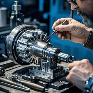
Top Proto delivers rapid prototyping services for engineering teams and product developers who need physical parts produced quickly from CAD files at the early stages of the design process. We produce prototype parts using CNC machining, 3D printing, vacuum casting, and sheet metal fabrication, selecting the process that best matches your part geometry, material requirements, and timeline. Every prototype is produced from your verified CAD file and delivered with dimensional inspection documentation confirming that critical features meet your drawing specifications.
Rapid prototyping refers to a group of manufacturing methods used to produce physical parts from digital CAD models in the shortest possible time, typically for design validation, functional testing, regulatory submission, or stakeholder review. The defining characteristic of rapid prototyping is speed — reducing the time between a CAD design and a physical part in hand — combined with the flexibility to produce parts without the hard tooling investment required for production manufacturing.
At Top Proto, rapid prototyping is not limited to a single process. We select the most appropriate process for your part based on its geometry, required material properties, surface finish specification, quantity, and delivery timeline. CNC machining produces the most accurate metal and plastic prototypes with real production material properties. 3D printing produces complex geometries with internal features that machining cannot reach. Vacuum casting replicates injection-molded appearance and properties for small quantities of plastic parts. Sheet metal fabrication produces functional metal enclosures, brackets, and panels from flat stock. In many programs, we combine two or more of these processes to produce a complete prototype assembly.
Why Choose Top Proto for Rapid Prototyping Services?
Top Proto operates CNC machining, 3D printing, vacuum casting, and sheet metal fabrication within a single facility in Shenzhen, China. This means a prototype assembly requiring machined metal components, printed plastic housings, and formed sheet metal covers can be produced, inspected, and assembled without shipping parts between suppliers. The result is a shorter total lead time and a single point of contact for your entire prototype program.
Our engineering team reviews your CAD files for manufacturability before production begins and recommends process changes where a different approach would reduce lead time, cost, or dimensional risk without compromising the test objectives. We produce prototype parts from production-grade materials wherever possible, so the data you collect from prototype testing reflects the actual behavior of your final design rather than a material surrogate.
Our Rapid Prototyping Services
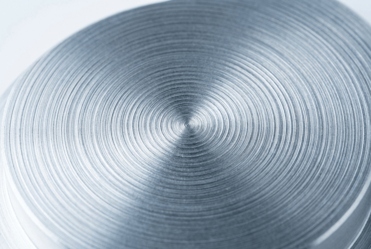
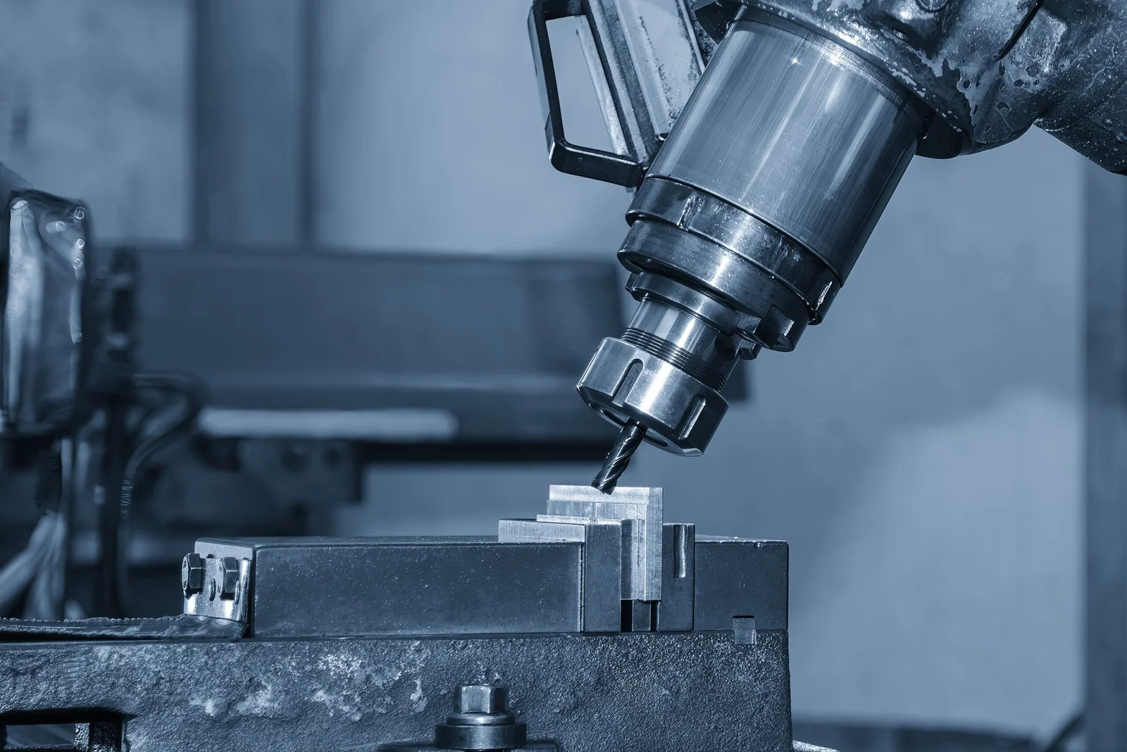
CNC Machined Prototypes
Machined from solid metal or plastic stock to your CAD file. Produces the highest dimensional accuracy of any prototyping process, with real production material properties. Suitable for functional mechanical testing, fit checks, and pre-production approval samples.
Up to 300 mm²/min (specific to material and thickness)
Surface Finish
As fine as Ra 0.2 µm
Maximum Cutting
Up to 12 inches (300 mm) – varies based on material
Wire Diameter
0.004 inches (0.1 mm) to 0.012 inches (0.3 mm)
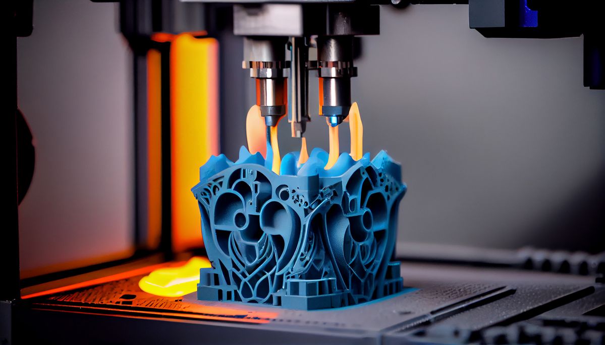
3D Printed Prototypes
SLA, SLS, and MJF additive manufacturing for complex geometries, internal channels, and design verification parts. Fast lead times for early-stage design validation where dimensional precision is secondary to geometric confirmation.
Silicone mold casting of polyurethane resin parts in quantities of 20 to 50 units. Produces injection-molding-quality surface finish and material properties from a master pattern without injection mold tooling investment.
Up to 2,000 rpm (depending on material and cutting tool)
Surface Finish
As fine as Ra $0.6$$\mu$m
Maximum Cutting
Up to 2 inches ($50$ mm)
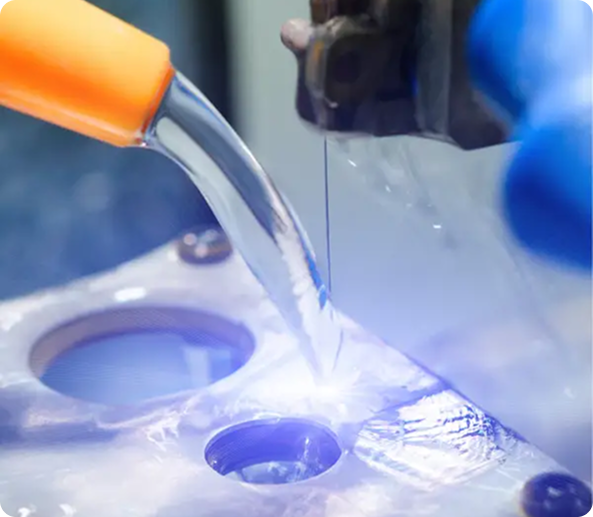
Sheet Metal Prototypes
Laser cut and press brake formed sheet metal prototype parts produced from your flat pattern drawings. Suitable for enclosures, brackets, structural panels, and assemblies requiring formed metal geometry for functional testing.
Feature
Specification
CNC Machining Lead Time
3 to 7 business days for standard metal and plastic prototype parts
3D Printing Lead Time
1 to 3 business days for SLA and MJF parts; 3 to 5 days for SLS
Vacuum Casting Lead Time
7 to 12 business days including master pattern production and mold pouring
Sheet Metal Lead Time
3 to 7 business days for laser cut and bent sheet metal prototypes
CNC Tolerance
Standard +/-0.01mm; precision down to +/-0.005mm on critical features
3D Printing Accuracy
Layer resolution 0.05mm to 0.1mm depending on process and resin
Vacuum Cast Accuracy
+/-0.3 percent of nominal dimension; minimum +/-0.2mm
Minimum Order
1 piece per process; no minimum order quantity for prototype programs
File Formats Accepted
STEP, STP, STL, IGES, DXF, DWG, SolidWorks, CATIA, and most major CAD formats
Which Rapid Prototyping Process is Right for Your Part?
Item
Details
CNC Machining
Best for: metal prototypes, tight tolerances, real material properties, functional mechanical testing. Use when dimensional accuracy and material performance are critical and geometry is achievable by cutting.
SLA 3D Printing
Best for: smooth surface finish, fine detail, visual models, and pre-vacuum casting masters. Use when geometry is complex but functional testing of mechanical properties is not a primary requirement.
SLS 3D Printing
Best for: functional plastic prototypes, complex internal channels, living hinges, and snap-fit features. Produces parts in Nylon PA12 with good mechanical properties without support structures.
MJF 3D Printing
Best for: high-detail functional Nylon prototypes with consistent mechanical properties throughout the part. Better surface finish and more uniform density than SLS, suitable for functional testing programs.
Vacuum Casting
Best for: small quantities (20 to 50 parts) of plastic prototypes with injection-molding-quality surface finish and near-production material properties. Best used after design is frozen and before production tooling is committed.
Sheet Metal Fabrication
Best for: metal enclosures, brackets, panels, and structural assemblies requiring formed geometry. Produces functional prototypes from production-grade sheet metal in the same materials and thicknesses as the final production parts.
As Machined
CNC machined prototype surface with visible tool marks and Ra 3.2 finish. Most cost-effective and fastest option for functional testing where appearance is not a requirement.
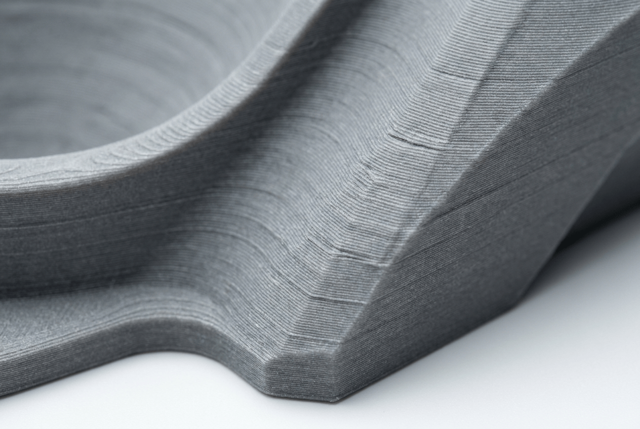
As Printed
3D printed surface with visible layer lines for SLS and FDM processes, or smooth resin surface for SLA and MJF. Suitable for geometric validation and early-stage design review.
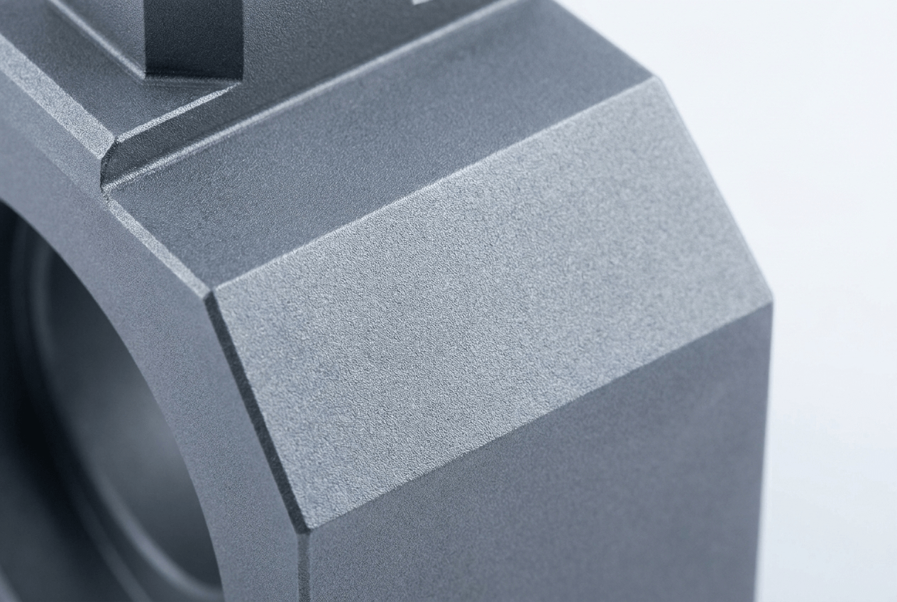
Bead Blasted
Applied to machined metal or 3D printed prototypes to create a uniform matte surface texture. Removes tool marks and layer lines, producing a consistent appearance for design review and photography.
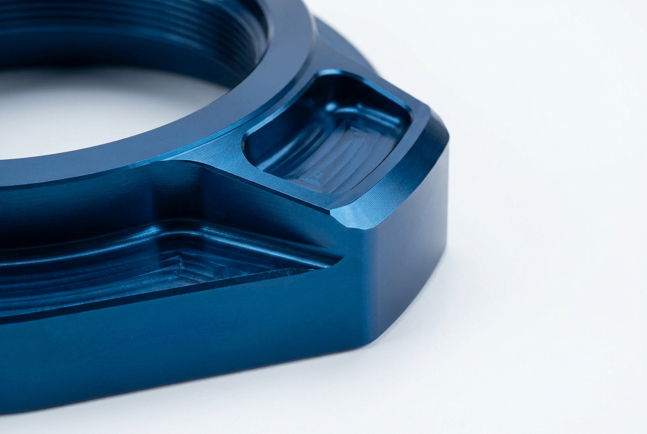
Anodizing
Applied to machined aluminum prototypes for corrosion resistance, surface hardness, and color. Produces a representative appearance of the production anodized part for design approval and marketing samples.
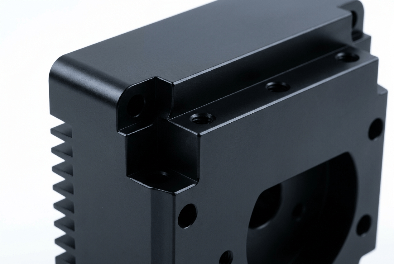
Painting
Post-process painting applied to machined metal, 3D printed, or vacuum cast prototypes for color matching, multi-color schemes, and cosmetic appearance evaluation.
Polishing
Manual or mechanical polishing applied to machined metal or SLA printed prototypes to reduce surface roughness and produce a smooth, reflective appearance for optical, medical, or cosmetic evaluation.
Rapid Prototype Surface Finishes
Industry Expertise at Top Proto
Top Proto has direct production experience across nine industries, each with its own dimensional tolerance standards, material certification requirements, and quality documentation expectations. We do not apply a generic machining approach to every sector — our engineering team reviews your industry-specific requirements before production begins and applies the process controls, material sourcing, and inspection methods appropriate for your application.
Rapid prototyping at Top Proto does not require hard tooling for CNC machining, 3D printing, or sheet metal fabrication. For vacuum casting prototypes, silicone mold tooling is produced from your master pattern in one to three days. This tooling approach eliminates the cost and lead time of hard tooling at the prototype stage, allowing design changes to be incorporated quickly without tooling modification cost.
Production Tooling
When prototype testing is complete and your design is ready for production, Top Proto manages the transition from rapid prototyping to production manufacturing within the same facility. Injection mold tooling, die casting dies, and progressive stamping dies are designed and produced by our tooling team using the same CAD data validated during the prototype program, maintaining dimensional continuity from prototype to production.
Made in China. Precision You Can Rely On.
Top Proto operates from Shenzhen, Guangdong, China — the global hub for precision manufacturing, advanced component supply chains, and technology production. Our facility houses over 300 CNC machining centers, injection molding presses, sheet metal fabrication lines, and 3D printing systems operating under a unified ISO 9001:2015, ISO 13485, IATF 16949:2016, and AS9100D certified quality management system. Skilled technicians and meticulous in-process inspection at every production stage ensure that custom metal and plastic parts are delivered to specification — with the dimensional inspection reports to prove it.
300+
Machines Running at Peak Efficiency
0.005mm
Ultra-Fine Tolerances Achievable
24 Hrs
Lead Times Starting From
50+
Engineering Materials Available
Choose Us for Flexible Pricing and Quick Delivery
At TOP PROTO, we know price and timeline go hand in hand. Our CNC machining services can work around your budget and deliver on your deadline. Get a quote instantly and select the service to meet your requirements.
Get quick pricing and DFM insights to optimize designs and reduce costs.
Global Supply Network
Access our global manufacturing network for reliable solutions of all sizes.
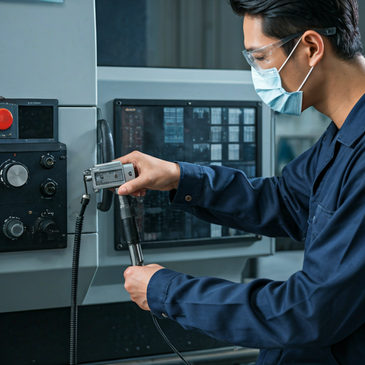
Certified Quality Control
Strict inspection protocols for every part. We ensure 100% accuracy and high standards.
Fast Reliable Delivery
Punctual shipping for all custom orders. Your projects always stay on schedule.
Pros of Top Proto
High Accuracy & Detail:Our milling process ensures that every component is cut to exact specifications, delivering a smooth, high-quality surface finish.
Isotropic Mechanical Strength: Milled components are robust in every direction, making them ideal for high-volume production runs that require consistent structural integrity.
Material Efficiency:Precision cutting paths minimize waste, and any unused material can often be repurposed or recycled efficiently.
Complex Geometries:Advanced 3-axis and 5-axis milling eliminate the need for complex support structures, allowing for intricate designs to be manufactured directly.
How We Works – 3-Stages Workflow
We guarantee that CNC parts are delivered on time and that the process is completely transparent in the following 3 simple steps:
Upload Your Files
Instant prices with DFM feedback for many file types.
We Manufacture Your Parts
You can select from many materials and methods.
Tracking and Receiving Your Parts
View the QC documentation and inspection photographs.
Frequently asked questions
Q: How quickly can I receive prototype parts?
Lead times depend on the process and part complexity. CNC machined prototypes are typically ready in 3 to 7 business days. 3D printed parts are ready in 1 to 5 business days depending on the process. Vacuum cast prototypes take 7 to 12 business days including master pattern and mold production. Sheet metal prototypes take 3 to 7 business days. Expedited lead times are available for urgent programs.
Which prototyping process produces the most accurate parts?
CNC machining produces the highest dimensional accuracy, with tolerances down to +/-0.005mm on critical features. It also uses real production material grades, making it the best choice when functional testing of mechanical properties is required. 3D printing and vacuum casting produce less dimensionally accurate parts but enable geometries and quantities that machining cannot produce cost-effectively.
Can you produce a complete prototype assembly with multiple parts?
Yes. Top Proto produces complete prototype assemblies combining parts from different processes — machined metal structural components, 3D printed plastic housings, and sheet metal covers can all be produced and assembled in our facility. Our engineering team coordinates the production sequence and tolerance stack-up across processes to ensure parts assemble correctly.
Do prototype parts have the same properties as production parts?
CNC machined prototypes produced from the same alloy and temper as the production specification have essentially the same mechanical properties as production machined parts. 3D printed and vacuum cast prototypes use different materials that simulate production resins but do not exactly replicate all mechanical properties. The degree of material match depends on the resin formulation selected and the production material being simulated.
What file format do I need to submit for a prototype quote?
We accept STEP, STP, STL, IGES, DXF, DWG, and most major CAD formats. STEP files are preferred for CNC machining and vacuum casting, as they preserve solid geometry and allow our team to generate tool paths accurately. STL files are accepted for 3D printing. DXF flat pattern files are preferred for sheet metal prototypes. A PDF drawing with tolerances and material specification should accompany your CAD file.
CNC Manufacturing Resources
Technical guides and process comparisons from the Top Proto engineering team, covering material selection, process decision frameworks, and manufacturing design principles for engineers and product developers.